Magneto Rheological Braking System

Description

In this project, We worked on design, analysis & fabrication of low cost MR fluid braking system which has performance advantage over conventional hydraulic systems, as well as provide a more environmentally friendly solution.

Aim and Objectives.

Conventional brakes have some disadvantages like wearing of brake pads, heating of parts, bulky size and heavy weight. The objective of this work was to design and fabricate a high-efficiency MR brake with high transmittable torque, good long-term stability and simple construction. MR fluid makes dramatic changes in their viscous and elastic properties in milliseconds when subjected to magnetic field. Variation in resistance to shear offered by MR fluid is rapid and almost reversible. These properties of MR fluid can be implemented in braking systems. Braking occurs due to viscosity of MR fluid which is induced due to its own composition and change in viscosity after application of magnetic field. The primary objective is to provide magnetic field by high power permanent magnets. Variation in magnetic field could be achieved by varying axial distance. Solenoid coil was another option in case use of permanent magnets are not suitable. The aim of the present study is to provide digital control on braking by reducing size of system for the same capacity by providing experimentally found data base for the present configuration. In order to fulfil above mentioned conditions following methodologies are adopted. 

  1. Literature review and study of design considerations. 
  2. Theoretical analysis and designed calculations. 
  3. Fabrication of Actual MR fluid operated Brake assembly.
  4. Actual experimental analysis. 
  5. Provide conclusions from entire experimental data. 

Design of MR Brake

In designing the MR brake, several factors are taken into consideration, including gaps, electromagnet, fluid behaviour, chamber and seals. The MR fluid is introduced into the brake via two holes in the flanged housing. It is confined within the chamber formed by the enclosure, housings, rotary plate and the seals. The ball bearings chosen are shielded on both sides to act as an additional seal for the MR fluid. The magnetic flux density in the gaps is provided by a electromagnet. 

Assembly of MR brakes 

Actual prototype. 

In above proposed design there are three major parts namely input flanged housing, cap and output flange. input flanged housing and cap forms closed cavity. Slotted disc rotates freely inside that cavity which was coupled to cap with help of bearing. Cavity in the form of slots was filled by MR fluid. Oil paper was used as gasket for leak proof joint. 

Actual Prototype

Design of Coils

Designed solenoid coil has following configurations. 

  • Inner radius of coil -: 80 mm. 
  • Length of solenoid coil -: 40mm. 
  • Copper wire -: 20 Gauge, insulated.
  • Current carrying capacity - 7 amp. 
  • Wire diameter - 0.56 mm.
  • No of turns -: 200 turns.

Insulated copper wire was wound on metal core (MS round pipe 80 mm ID, 4cm long). Wornish solvent was added while wounding to fill up the air gaps between wires which serves as coolant also. In order to provide safety fabric tape was wound around the coil. On both sides PVC flanges are placed and coupled. 

Experimental Setup.

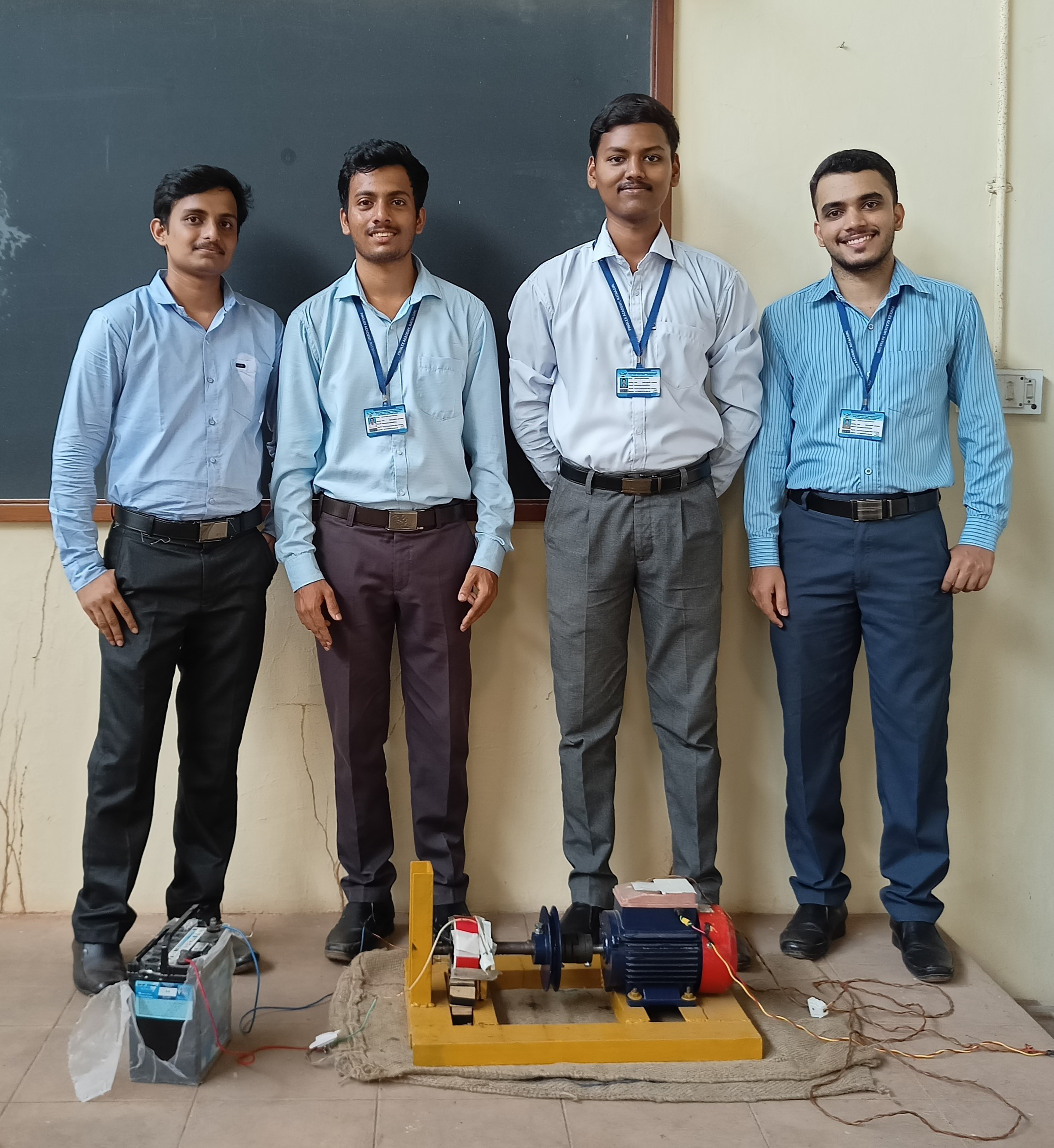
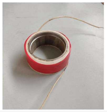
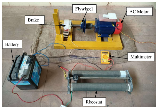
We set up the assembly as shown in the image. The MR brake is fixed in position by a bracket. A DC power supply and a multimeter are connected to both ends of the MR brake to provide the required current for flux generation and for measurement of the current. The shaft of the MR brake is connected to the flywheel through a connector and is rotated at the speed of the motor. 

A typical testing procedure is as follows. Firstly, the MR brake is rotated at a speed of 3000 rpm for 30 sec as an initial condition, which stirs the MR fluid in the brake to distribute it uniformly. The desired magnetic field is then applied by setting the coil current and waiting for 1 min, ensuring that the MR fluid is formed into a stable structure. After that, a steady rotary speed is provided to the brake shaft by adjusting the motor. Different set of readings are taken by applying brake for cach set of RPM and Current value. 

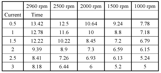
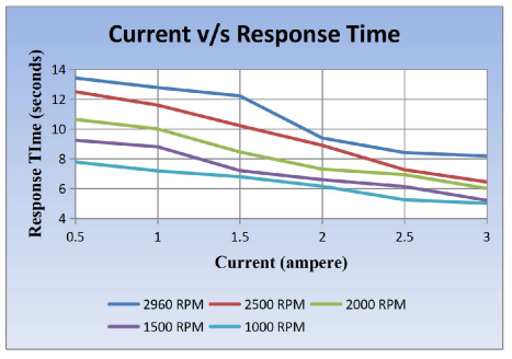
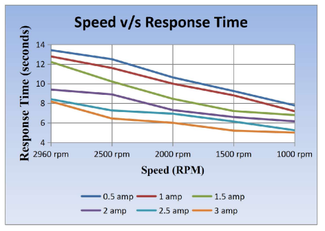
The MR brake performance under steady rotary condition was investigated using the test rig. In the experiment, five typical rotary speeds, i.e., 1000, 1500, 2000, 2500 and 2960 rpm, were used. The effects of magnetic field strength and rotary speed on the transmitted torques are studied and summarised in the following section. The speed of the flywheel is measured with the tachometer in contactless form. The voltage is kept constant and current is varied from 0.5 amp to 3 amp with a rheostat. The response time for braking for each set of reading is noted. 

Results and Discussion.

Following Table gives variation of reaction time with varying input current at input voltage of 12 volts. Graphical representation gives exact view of cumulative variation of response time. 

From the observationS, it can be seen that at constant voltage, the response time of braking system goes on decreasing with increasing current. Furthermore, the experiment also shows that there is a good corresponding relation between the braking torque and the current.

From this current v/s response time graph we concluded that with increasing current passing through the magnetic coil, the response time decreases. From the observation of graph, it is observed that braking torque generated by the MR brake was the function of current passing through the solenoid coil. While experimenting it was found that after certain value of solenoid input current temperature of the MR brake will increase drastically. Hence experimentation was limited to solenoid current value of 3 amps. 

Graphical representation of above Experimental data is as shown in figure. From graphical plotting it can be observed that at solenoid currents from 0.5 to 1.5 amp, decrease in the response time is almost steady. Above 2-amp input current, the response time drastically decreases. Hence, we conclude that with increasing speed of the input shaft, the response time of the MR brake increases and by increasing the value of input current, the response time also increases. 

Conclusion.

In this project, using an MR fluid as a control medium for a braking system, a simple, quiet, and rapid-response MR brake was designed and fabricated. The brake performance was experimentally evaluated by using a designed test rig. The main findings are summarized as follows: 

  • The transmitted torque increases gradually with increasing magnetic field strength except for field saturation. It also shows an increasing trend with rotary speed.
  • An amplifying factor is introduced to evaluate the brake performance, which can beincreased by either increasing the magnetic field strength or reducing the rotary speed. 

The proposed MRB presents the advantages of a compact size, a high quality, a low power consumption and a rapid response time. On the whole, the MRB is the result of a promising technology for vehicular applications.  

The research clearly explains that solenoid current plays vital role in determining MR torque generated by MR fluid. Design of MR fluids applications basically depend upon effectiveness of solenoid coil. Permanent magnets can be used as source of magnetic flux but positioning is such case is troublesome. 

Department of Mechanical Engineering

Finolex Academy of Management & Technology, Ratnagiri

2021-2022

Submitted by:

Mr. Ashutosh Vijay Mandavkar.

Mr. Swaroop Sandeep Joshi.

Mr. Varad Dattatray Natekar.

Mr. Chinmay Dilip Vanaju.

Built with Dorik